Folded edges
The fault surfaces in your fault model should not have sharp bends or kinks on the individual fault surfaces. During further modeling, local kinks or sharp bends in a tri-mesh may lead to unexpected results and/or issues, such as holes in your 3D structural model. If processing issues do occur, complex geometries may be one of the causes.
You review the geometry of your faults in respect to sharp bends with the 'Folded edges' test. You specify a maximum angle between two adjacent triangles of a tri-mesh; all angles below this value will be considered 'folded edge'. A completely flat tri-mesh would have angles of 180°, a right angle is 90° and triangles folded onto itself would show angles of 0°. Triangles of tri-meshes in your fault model should not have angles below 90° and stay well above this value.
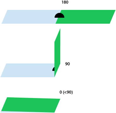
Measuring principle for the angle between adjacent triangles. click to enlarge
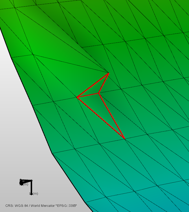
Example of a folded edge. A local angle around 85° is detected in this example. The two triangles that are creating a folded edge are highlighted in red in the Diagnostic View. click to enlarge
Not all folded edges lead to processing artifacts and it may not be required to remove the issues. If the folded edge is not intended and is to be removed, you have a few options to resolve the issue depending on the location and the cause of the folded edge. The folded edges can be introduced at different steps in the workflow:
- Fault surfaces generated from fault sticks may produce sharp bends when neighboring fault sticks are not consistent. In this case, please review your fault sticks in the context of your seismic interpretation. Update your fault sticks to obtain a smoother surface. Please note that changes in your seismic interpretation require you to re-assign your adjusted fault(s) to your fault model.
- Fault surfaces generated from fault sticks may show undesired bends based on the surface interpolation settings applied in the Seismic Interpretation workflow (prepare > Seismic). Review the interpolation settings and re-run the surface generation. The changes in your Seismic Interpretation need to be propagated in the workflow, re-assign your adjusted fault(s) to your fault model.
- The resampling of the faults in the Assign Data step in the Fault Modeling workflow can, in rare cases, introduce folded triangles. In addition, imported data can have folded edges to begin with. Other than changing the modeling parameters or choosing not to resample, you can edit the input tri-meshes or the fault tri-meshes in the fault model with the editing tools. Examples on how to do this are given below. If your fault model has already been assigned to a structural model, you need to re-assign the adjusted fault model.
Solving the issue using the editing tools
To manually remove a folded edge you can use a variety of editing tools on the tri-mesh.
- If the folded edge is only caused at a single location leading to a local spike, you can smooth the surface by just interacting with a single node. Use the Move Node tool
 to move the node into the desired location, or remove the node altogether by using the Remove Node
  tool. The latter will collapse the node and reconnect the triangle connections.
 - Other options are in some cases to flip the triangle’s edges (Flip Triangle Edge
 ). For larger affected areas, you can also delete one or more triangles and fill the gap with the Fill Hole
  tool as shown below.
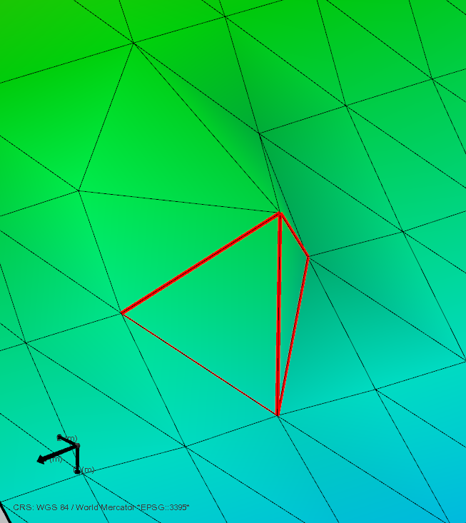
The two triangles that are creating a folded edge are highlighted in red in the Diagnostic View. click to enlarge
The local spike is removed by deleting the surrounding triangles. click to enlarge
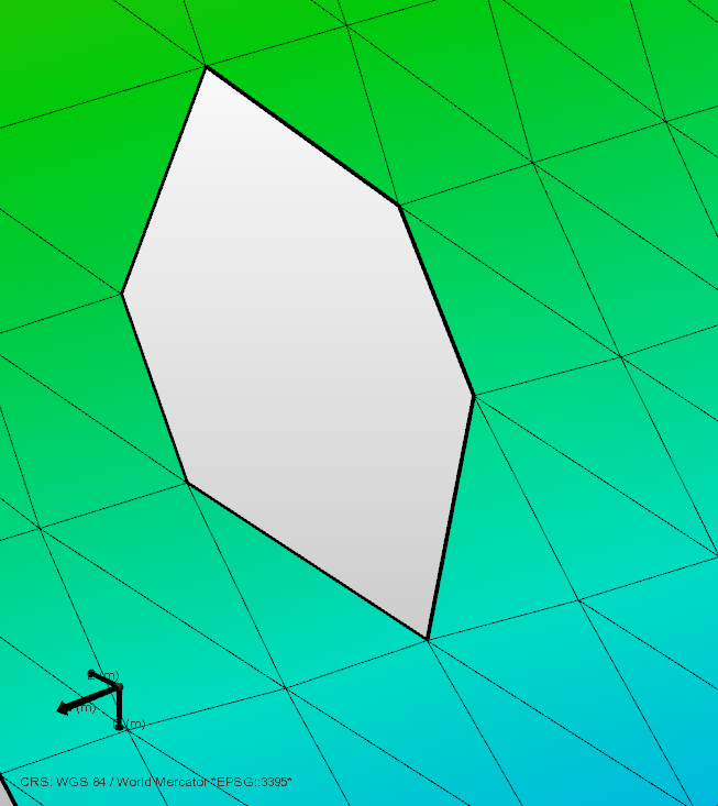
The created hole is then filled with the Fill Hole tool. click to enlarge